Installing an Automatic Watering System Part 1: Building the Soil Moisture Sensor


If you are a keen gardener, you will be well aware of the need to keep your flowers and vegetables hydrated, and of how much time this takes using a watering can. The alternative is to set up an automatic watering system. Automatic watering timers are widely available, but I wanted one that would respond to soil moisture, not just the time of day.

Aims

  • Set up a watering system to respond to soil moisture levels.
  • For this we will need an outside tap, hosepipes, leaky pipe or sprinklers. And a water control valve. We will start by building a LoRa connected soil moisture sensor.

Research

Equipment

My shopping list included the following items:

Items also needed, but can also be used on other projects

Procedure

First, connect your Arduino MKR WAN to your TTN account by following the procedure here.

If you wish to connect to an application such as Home Assistant using MQTT, then read this.

Next, collect together all the items listed above ready for assembly. 

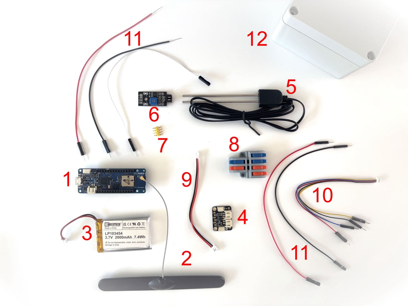
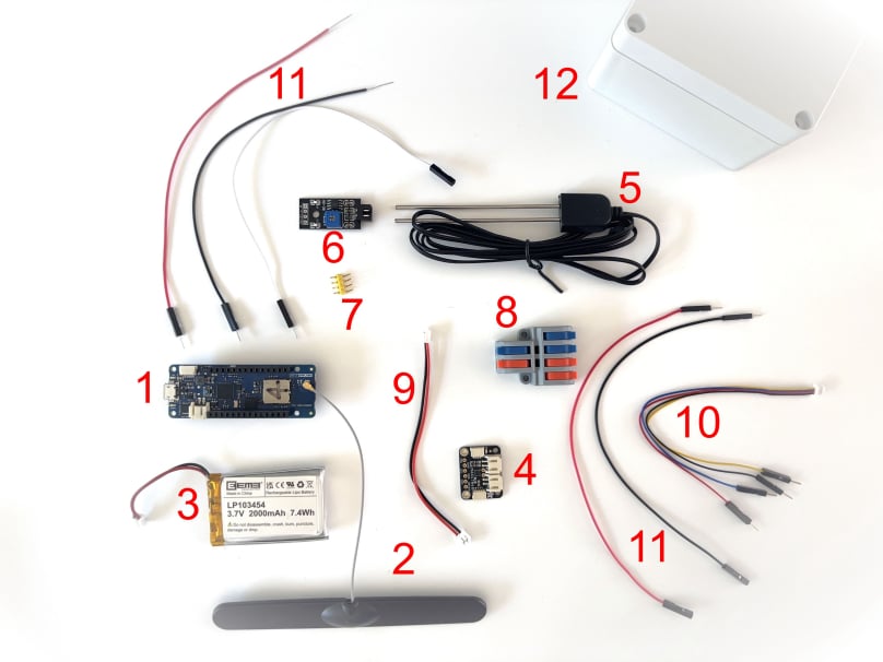
The components

What’s in the picture:

1. MKR WAN 1310.
2. Antenna.
3. Battery
4. Fuel gauge and battery monitor.
5. Soil moisture probe.
6. Soil moisture sensor.
7. Connector pins.
8. One input to two output connector.
9. JST-PH 2-pin jumper cable.
10. I2C Qwiic Stemma QT cable.
11. Jumper wires, 2 black and 2 red for GND and VCC, and one white for sensor wire.
12. Waterproof junction box.


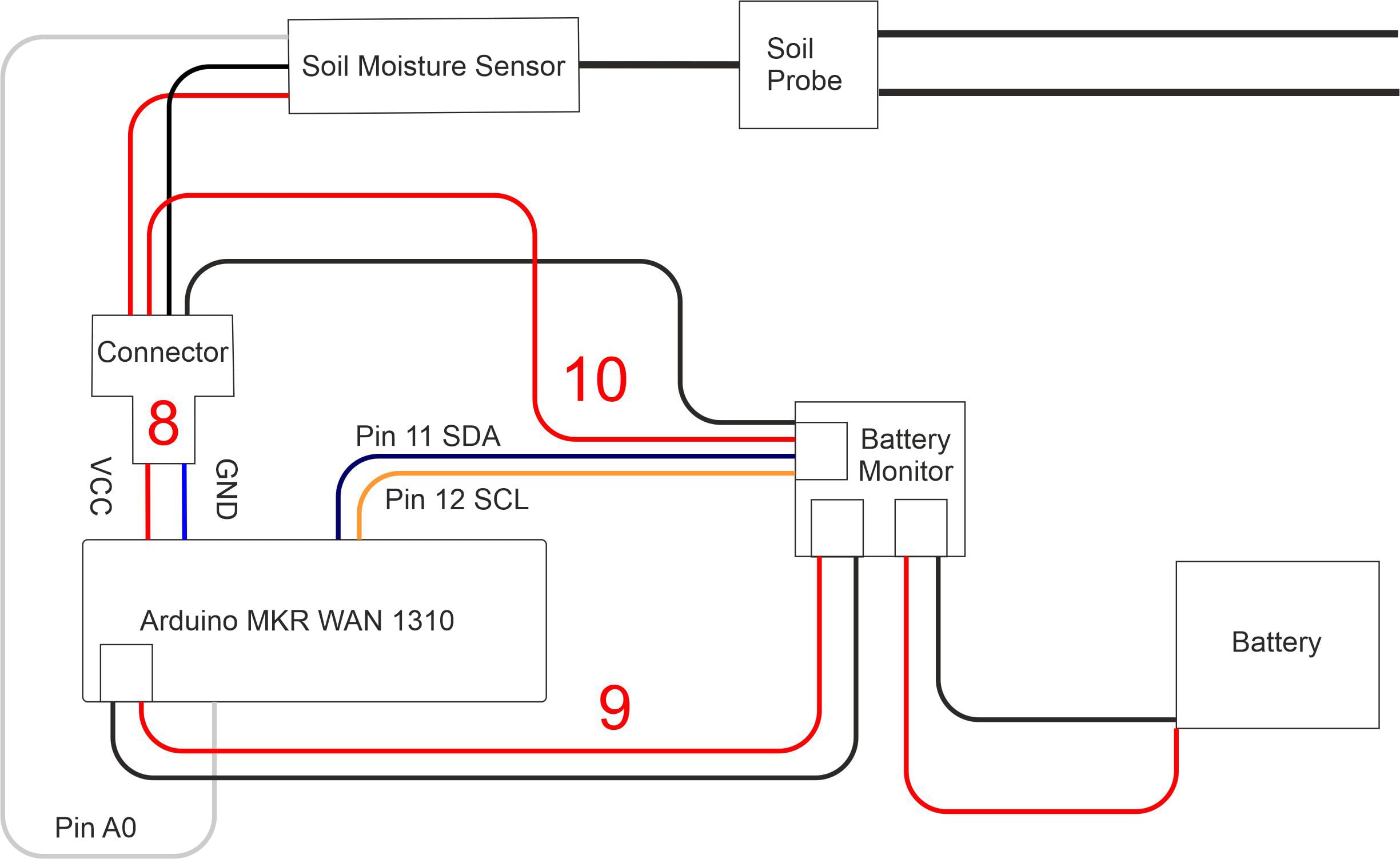
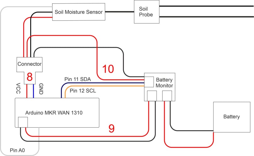
Here is a schematic that shows how the components are to be connected:

Soil moisture sensor wiring

The numbers in red refer to the same components that are numbered in the previous image. So, ‘8’ refers to the one input to two output connector, ‘9’ is the JST-PH 2-pin jumper cable, and 10 is the I2C Qwiic Stemma QT cable.

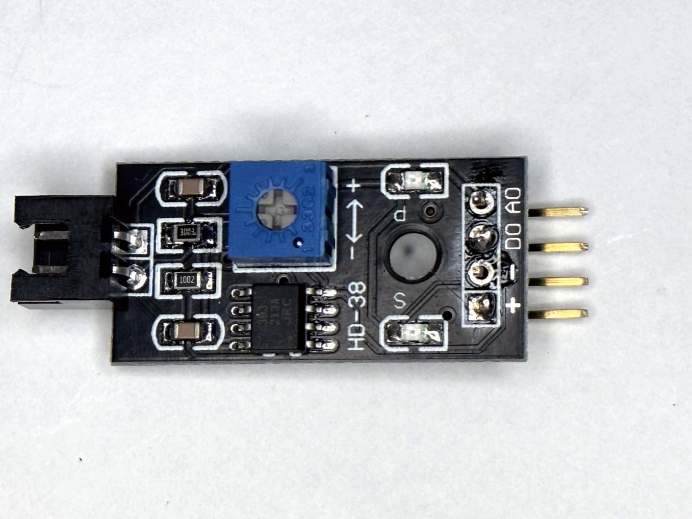
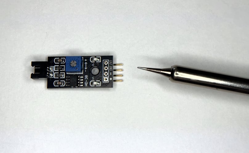
The connector pins (number ‘7’ in the previous image) will need to be soldered on to the soil moisture sensor (labelled ‘6’ in the previous image) before you can connect the jumper cables.

Soldering on the pins

Before we can start to assemble the components, we are going to solder the pins to the soil moisture sensor. Place the shorter end of the pins into the holes in the moisture sensor. You will need a fine point on your soldering iron.

Turn on the soldering iron and place the tip of the iron onto the metal circle surrounding the pin. After a few seconds apply the solder. Don’t apply too much solder, or you will short out the pins.  


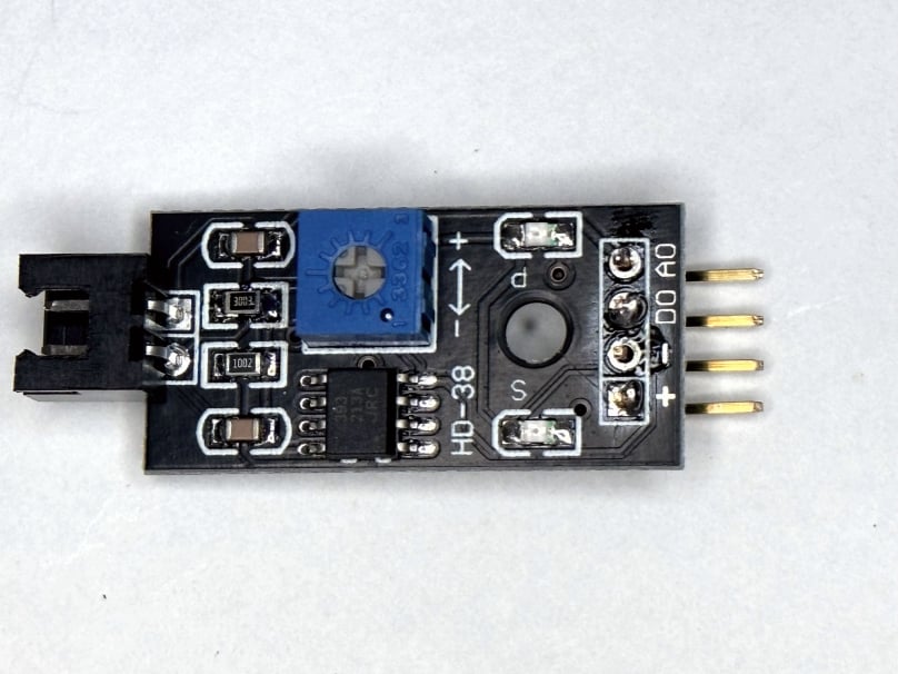
The pins soldered

I just applied enough solder to stop the pins falling out, I didn’t bother to solder one of the pins at all (GND). It still seems to work.


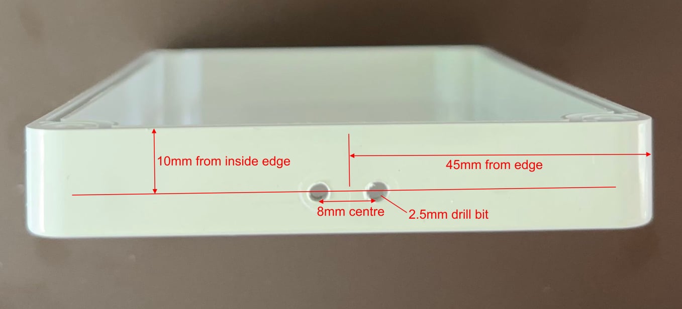
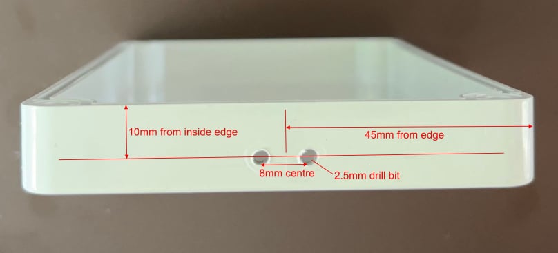
Measuring the holes

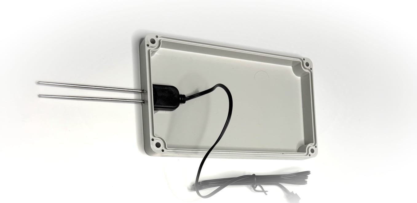
We need to drill some holes in our waterproof junction box so that the ‘legs’ of the moisture probe can protrude from the box. It is easiest to put the probe in the lid of the box. See the image below for the spacing you will need between the ‘legs’.


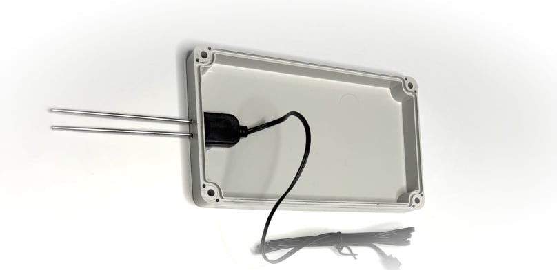
Lid with sensor

Check that the soil sensor fits through the holes. If not, you will need to adjust the opening using a file or a larger drill. Once you have a good fit, you can fix the sensor in place using a waterproof glue.

I used EVO-STIK Serious Glue, which claims to be high strength and waterproof (and a non-conductor of electricity). Put some glue under the body of the moisture sensor, then press down so that the ‘legs’ are pushed all the way through the holes and the back of the sensor is firmly against the top of the junction box. Hold this in place for a few minutes while the glue ‘sets’, and then don’t move it for a couple of hours while the glue hardens. 

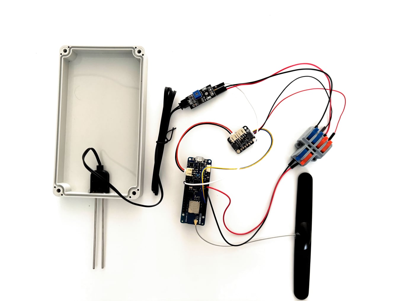
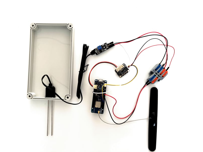
Sensor assembled

If you connect up the components, you should see something like this.

Note that the battery is not connected in this image. Before connecting the Arduino to your computer, connect the battery; otherwise, you may see inaccurate or unexpected readings in the Arduino IDE Serial Monitor. Once the battery is connected, connect the Arduino to your computer using the micro USB cable to verify that everything is working correctly.


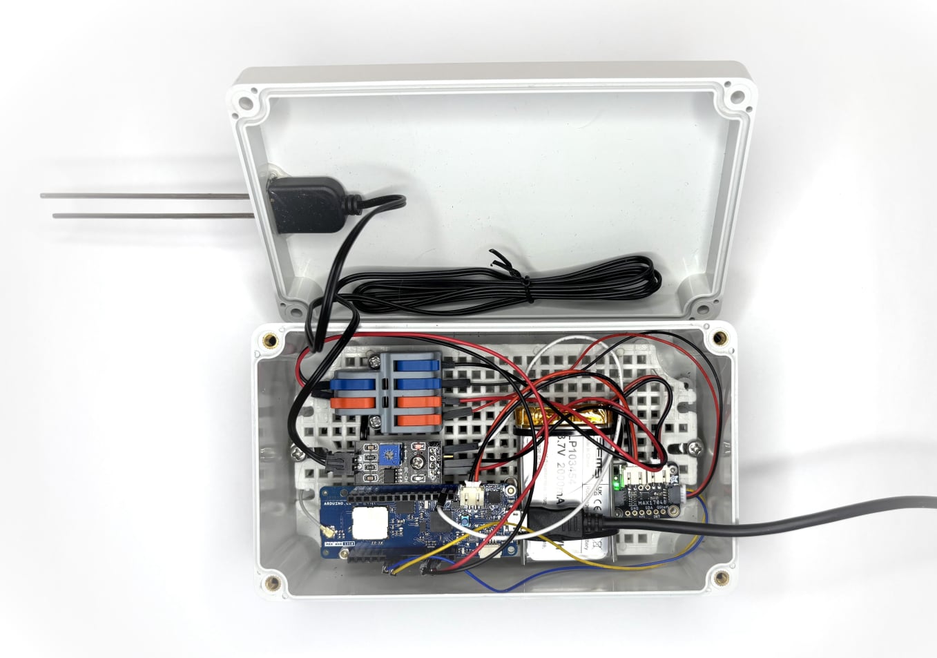
If you have bought a junction box with a mounting plate, then you can mount the components on that. You will need some standoff screws (see shopping list above) and some cable ties for the ariel and battery. This is what I used.

For the wire splitter connector:

2 x M3 x 10mm screws
2 x M3 nuts

For the soil moisture sensor: 

1 x M3 x 10 + 6 standoff screw
1 x M3 nut
1 x M3 + 6 screw

For the battery monitor:

4 x M2 x 8mm screws
4 x M2 x 15mm standoff screws
4 x M2 washers
4 x M2x 5mm screws

For the Arduino MKR WAN 1310:

4 x M2 x 8mm screws
4 x M2 x 20mm standoff screws
4 x M2 washers
4 x M2x 5mm screws

And four 12mm cable ties.

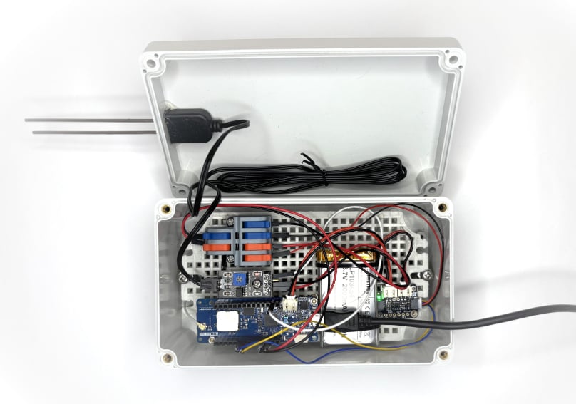
Sensor in enclosure

Once the components have been secured to the mounting plate, you should have something like this.

Now it is time to see if it all works. Make sure that the battery is connected to the battery monitor and then connect the Arduino to your computer using the micro USB cable.

We need to connect your Arduino to your TTN account, if you have not already done so. Click here for instructions.

We are now going to open a sketch in your Arduino IDE, which will take soil moisture readings and upload them to your TTN account. Here is the sketch, but you can also download it from GitHub here. 

// For LoRa:
#include <MKRWAN.h>
// For battery monitor:
#include "Adafruit_MAX1704X.h"
Adafruit_MAX17048 maxlipo;
// For battery charger
#include <Arduino_PMIC.h>
// For LowPower
#include "ArduinoLowPower.h"

LoRaModem modem;

// Please enter your sensitive data in the arduino_secrets.h tab
#include "arduino_secrets.h"

// Start of soil moisture code...
// initiialise some variables
// the sensor value is taken from the sensor pin (A0)
int sensorPin = A0;
int sensorValue;
int dryAnalogValue = 1023;
int wetAnalogValue = 0;
int DryValuePercent = 0;
int WetValuepercent = 100;
// ...end of soil moisture code

// initialises a variable for battery state of charge:
int cellPercent = 0;

// We need the details below to connect your device to LoRa
// Read arduino secrets
String appEui = APP_EUI;
String appKey = APP_KEY;

void setup() {
// Put your setup code here, to run once:

// Start of battery charger code...
if (!PMIC.begin()) {
Serial.println("Failed to initialize PMIC!");
while (1);
}

// Set the input current limit to 2 A and the overload input voltage to 3.88 V
if (!PMIC.setInputCurrentLimit(2.0)) {
Serial.println("Error in set input current limit");
}

if (!PMIC.setInputVoltageLimit(3.88)) {
Serial.println("Error in set input voltage limit");
}

// set the minimum voltage used to feeding the module embed on Board
if (!PMIC.setMinimumSystemVoltage(3.5)) {
Serial.println("Error in set minimum system volage");
}

// Set the desired charge voltage to 4.11 V
if (!PMIC.setChargeVoltage(4.2)) {
Serial.println("Error in set charge volage");
}

// Set the charge current to 375 mA
// the charge current should be defind as maximum at (C for hour)/2h
// to avoid battery explosion (for example for a 750mAh battery set to 0.375 A)
if (!PMIC.setChargeCurrent(0.375)) {
Serial.println("Error in set charge current");
}
Serial.println("Initialization done!");

if (!PMIC.enableCharge()) {
Serial.println("Error enabling Charge mode");
}
// End of battery charger code.

Serial.begin(9600);
while (!Serial && millis() < 10000); //This line is needed to work with batteries https://forum.arduino.cc/t/it-does-not-work-powered-by-2xaa-batteries/520097/5

// The code below connects your device to LoRa
if (!modem.begin(EU868)) { // change this to your regional band (eg. US915, AS923, ...)
Serial.println("Failed to start module");
while (1) {}
};

Serial.print("Your module version is: ");
Serial.println(modem.version());
Serial.print("Your device EUI is: ");
Serial.println(modem.deviceEUI());
int connected = modem.joinOTAA(appEui, appKey);

// Start of battery monitor code...
Serial.println(F("\nAdafruit MAX17048 simple demo"));

if (!maxlipo.begin()) {
Serial.println(F("Couldnt find Adafruit MAX17048?\nMake sure a battery is plugged in!"));
while (1) delay(10);
}
Serial.print(F("Found MAX17048"));
Serial.print(F(" with Chip ID: 0x"));
Serial.println(maxlipo.getChipID(), HEX);
// ...end of battery monitor code.

if (!connected) {
Serial.println("Something went wrong; are you indoors? Move near a window and retry");
while (1) {}
}
}

void loop() {
// put your main code here, to run repeatedly:

// Start of soil moisture code...
sensorValue = analogRead(sensorPin);
Serial.println("Analog Value : ");
Serial.println(sensorValue);
sensorValue = analogRead(sensorPin);
Serial.print("Analog moisture Value : ");
Serial.println(sensorValue);
int moistureValuePercent = map(sensorValue, dryAnalogValue,
wetAnalogValue, DryValuePercent, WetValuepercent);
Serial.print("moisture percent: ");
Serial.print(moistureValuePercent);
Serial.println("%");
if (moistureValuePercent == DryValuePercent)
{
Serial.println("plant is dry !! ");
}
else
{
Serial.println("plant is OK !! ");
}
// ...end of soil moisture code

// Start of battery monitor code...
cellPercent =(maxlipo.cellPercent());
Serial.print(F("Batt Voltage: ")); Serial.print(maxlipo.cellVoltage(), 3); Serial.println(" V");
Serial.print(F("Batt Percent: ")); Serial.print(maxlipo.cellPercent(), 1); Serial.println(" %");
Serial.println();
// ...end of battery monitor code.

byte payload[2]; // The [2] means we are sending two items in the array. Arrays start at zero.
payload[0] = moistureValuePercent; // Send soil moisture by LoRa.
payload[1] = cellPercent; // Send state of charge by LoRa.

delay(1000); // Gives it time to execute.

modem.beginPacket();
modem.write(payload,2); // The number after the word 'payload' is the number of items sent in the array above. If you add another item, increment this number.
int err = modem.endPacket(false);
if (err > 0) {
Serial.println("Data Sent");
} else {
Serial.println("Error");
}
Serial.print("soil moisture data sent is: ");
Serial.print("soil moisture % is: "); Serial.println(moistureValuePercent);
Serial.print("battery % is: "); Serial.println(cellPercent);

LowPower.deepSleep(1800000); // 30 minute intervals. This is the line we will be using when the sensor is in production mode.
//delay(300000); // This is the interval between each temperature and state of charge reading. The default is five minutes.
//delay(30000); // We can use 30 seconds while in testing mode.

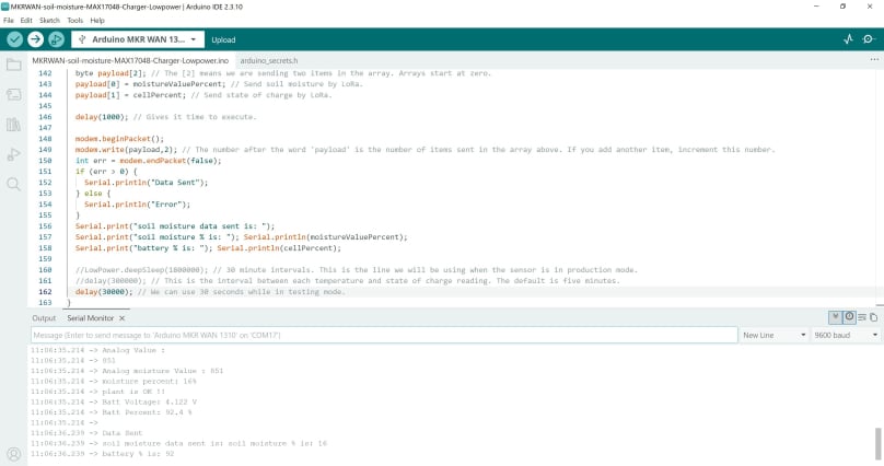
Arduino IDE

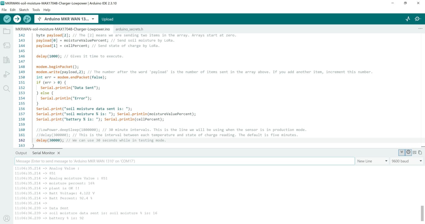
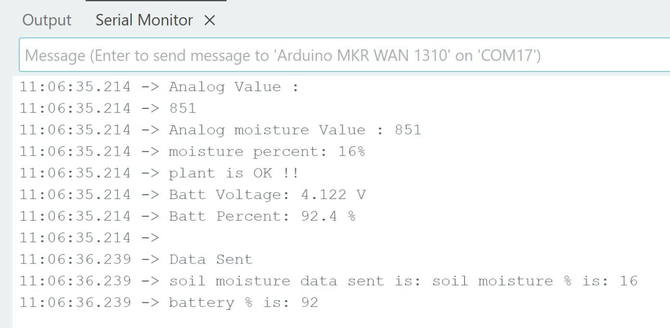
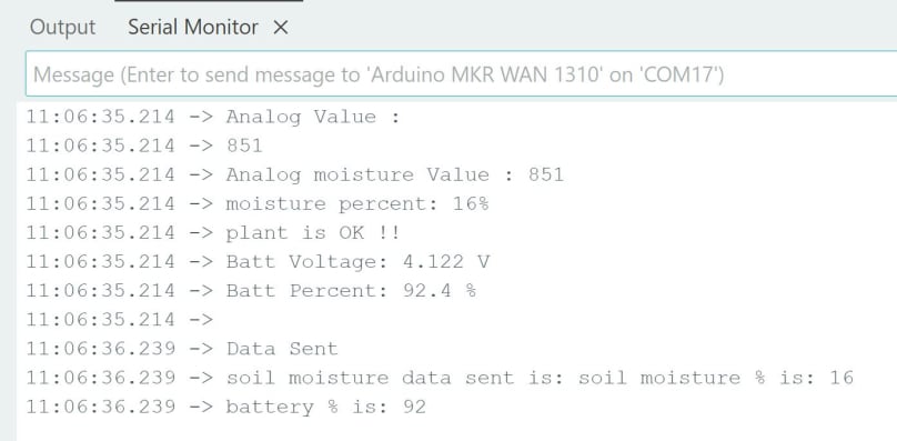
Once you have copied this sketch to your Arduino IDE, upload it to your Arduino MKR WAN. Make sure you have selected the correct board and port in the Tools tab of your IDE. When successfully uploaded you should see something like this in your serial monitor.


Serial monitor

For a close up.

In this image, the line ‘Data Sent’ tells us that the soil moisture and state of charge have been sent to TTN.

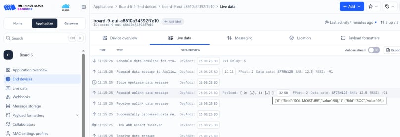
Results in TTN l

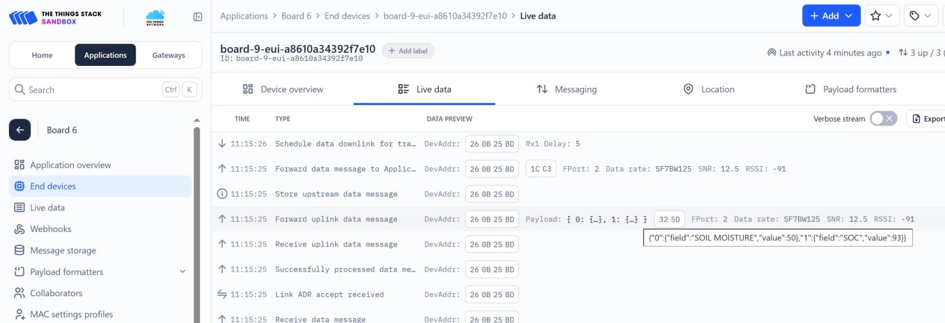
In order to view the data in TTN, go to your TTN account, go to ‘Applications’ and find your end device. Click on ‘Live data’ and you should see something like this.

If you mouseover the Payload line, you will see that in this case the soil moisture is 50% and the battery SOC is 93%.


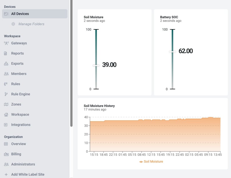
Datacake display

For data visualisation you can now connect your TTN application to Datacake by following the instructions here: https://loraworkshop.com/configuring-your-device-on-datacake-part-1.html.

Once you have connected your TTN device with Datacake, you can set up a dashboard to display you data by following these instructions: https://loraworkshop.com/configuring-your-device-on-datacake-part-2.html. No data will be displayed until this section has been completed.

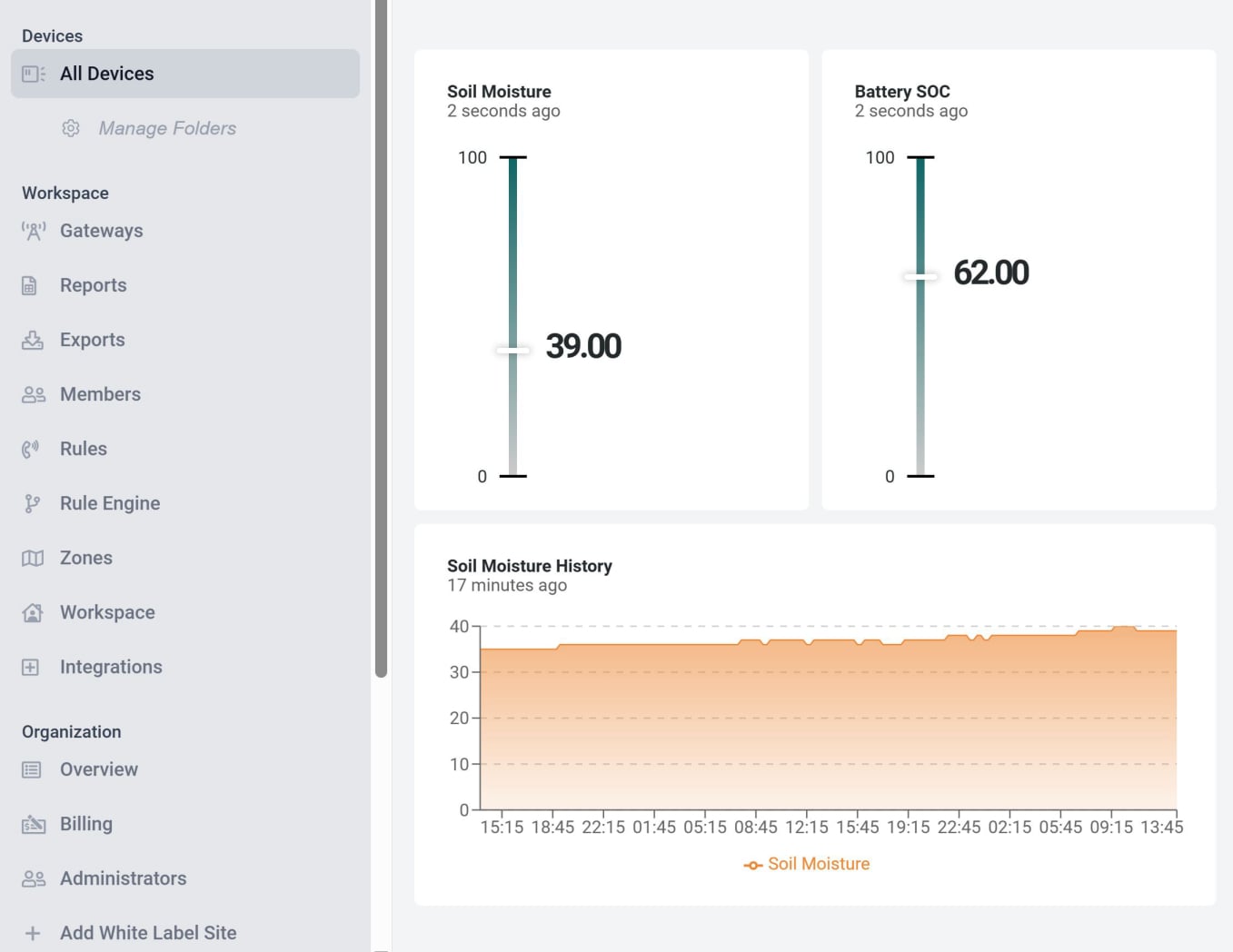
Here is a Datacake dashboard I set up earlier to show soil moisture content and the battery state of charge. 

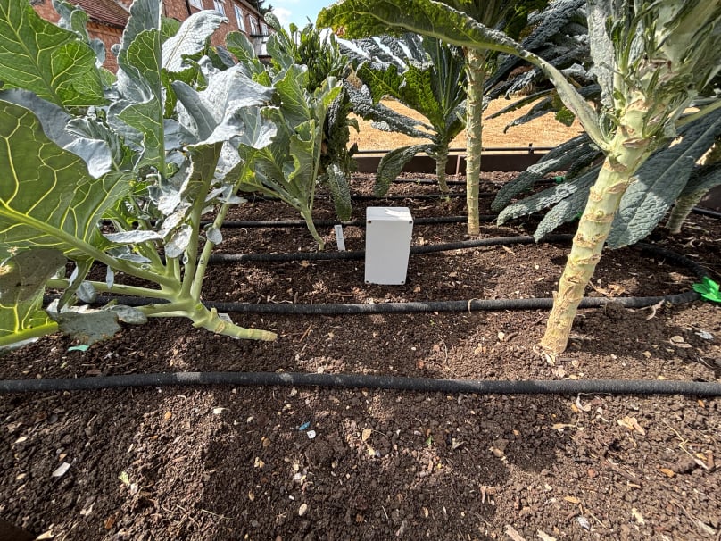
Cabbage patch

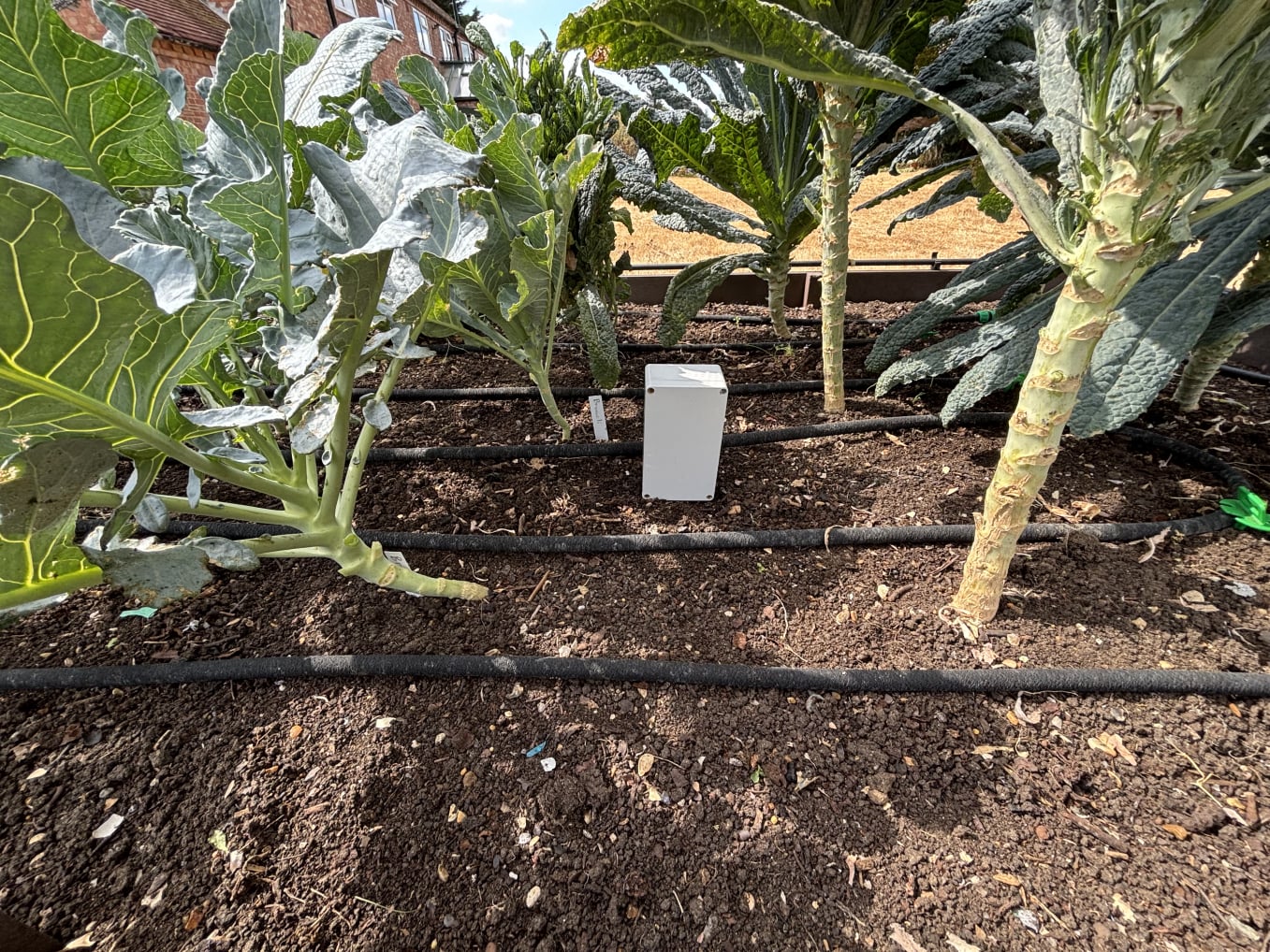
By now you should have your soil moisture sensor ready to deploy. This image shows a sensor released into the wild. To discover the soil moisture content of my cabbage patch, click here.


Now we have to act on the information received. In the next section we will build a water control valve, which can be automatically activated by our soil moisture sensor.

Next section coming soon.

© Copyright 2025 Dr Dulcamara - All Rights Reserved